
Below are images and guidance for installing the Engage Inferno.
Here are the details of the items you will recieve
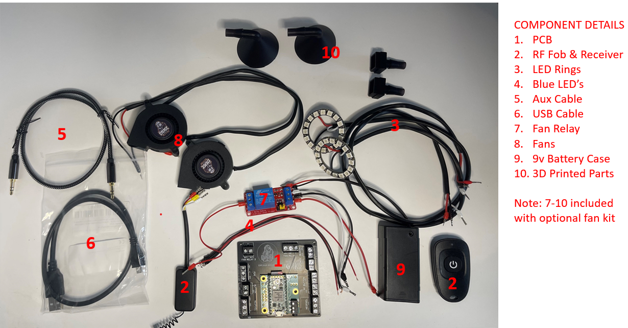
**NOTE – The 9v battery only powers the fans. A USB power pack will be needed to power the main unit (Light & Sound).**
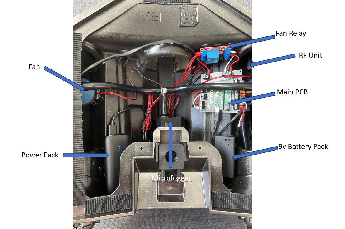
For installing I recommend using Velcro and a hot glue gun. Below is a guideline for my install. I’ll update it as necessary with any recommendations as I use my personal kit.
I recommend adding Velcro to the back of the main PCB & RF antenna unit, if you have the fan kit then adding Velcro to the relay & 9v battery case. Additionally I added Velcro to my power pack to prevent it moving around. Once your Velcro is glued to the units add the other side of the Velcro (intended to be glued into the Jetpack) onto the Velcro on your units. When ready you can add hot glue and then hold each component into position in the Jetpack.
The pictures used for this install are in the Mandalorian Rising Phoenix. However the principle should be similar in other jetpack models.
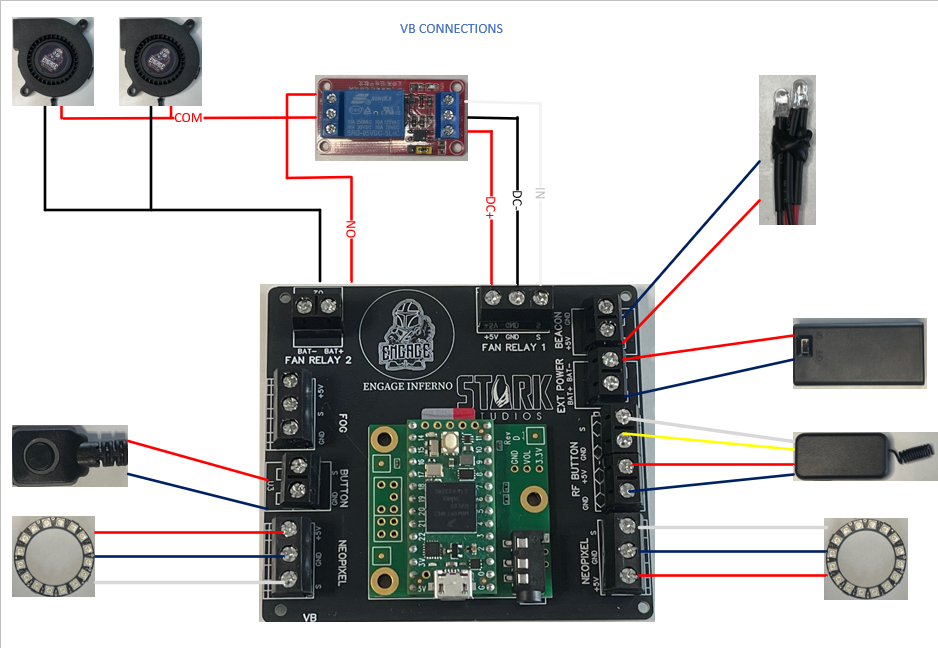
You can follow the below connectivity diagram (details are also on the PCB).
**When tightening the terminal block screws just tighten until there is resistance. Screwing down too hard will damage the wire connectors causing them to break.**
RECOMMENDED COMPONENT LOCATIONS
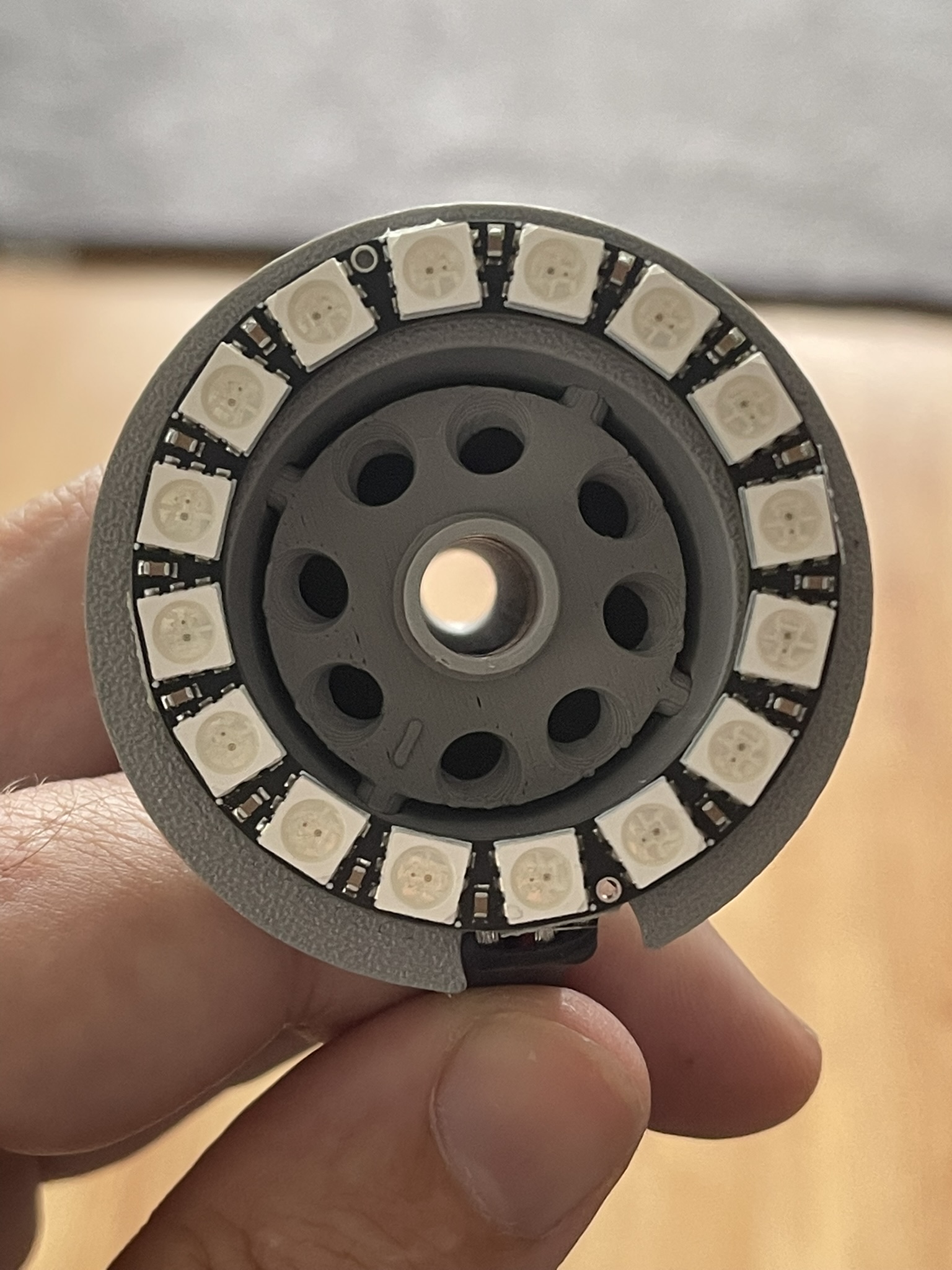
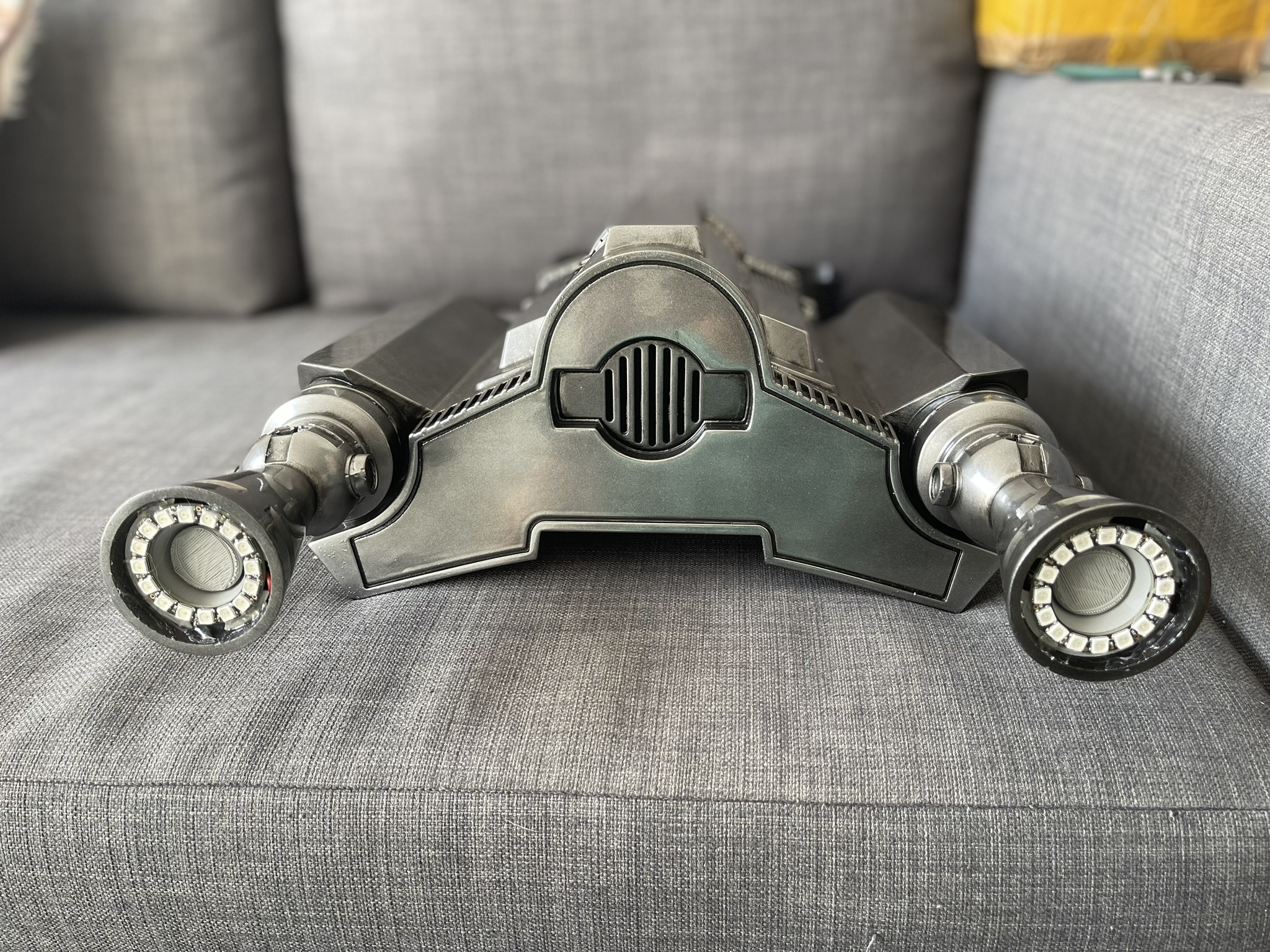
MOUNT LED RINGS & INSTALL BEACON
I recommend installing the LED rings and Beacon LED’s first and running the cables into the main housing ready to be connected. If using the smoke defusers then hot glue the LED’s on them first, attach your silicone hosing (don’t cut to length yet) and feed the hose & wiring into the main jetpack bay and then hot glue the defuser into the Jetpack boosters.
COMPONENT INSTALLS & LED CONNECTIONS
Then with the RF unit connected to the PCB (saves fiddling with connecting later) I recommend extending the aerial and placing it down into the booster housing.
You can now connect the LED rings (one will be longer than the other, use the longer one for the LED furthest away from the main unit) and Beacon LED’s to the PCB and mount and connect the relay if your also installing fans. The 9v battery case can also go in and be connected.
INSTALLING FANS
Installing the fans is a tricky part, I found Velcro wont work for these but instead found having them loose is a safer easier choice. Once attached to the Microfogger they will keep in place once positioned. Before installing the fans add the included 3D printed parts. The downward nozzle will hold in place within the fan (a small amount of sanding may be required to get it to fit snug). The funnel shaped nozzle needs to be hot glued onto the fan over the fan blades, then highly recommend adding hotglue to close up the seal and holes around the fan to prevent smoke from leaking out. It looks messy but ensures no smoke leaks out.
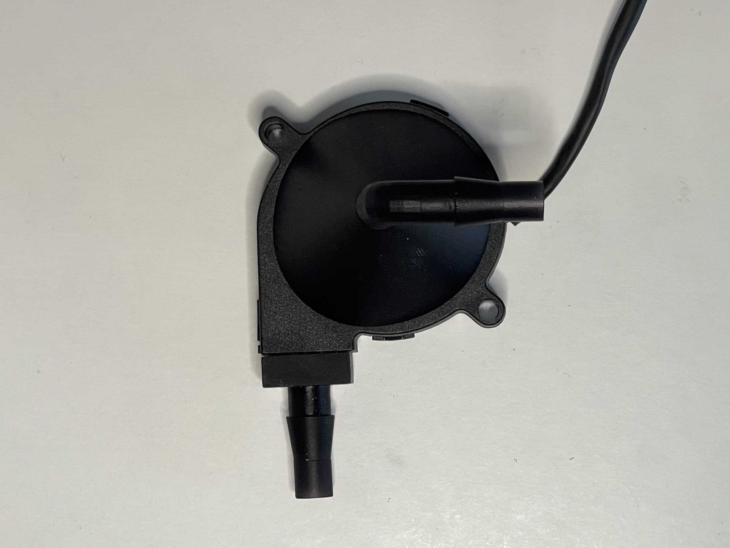
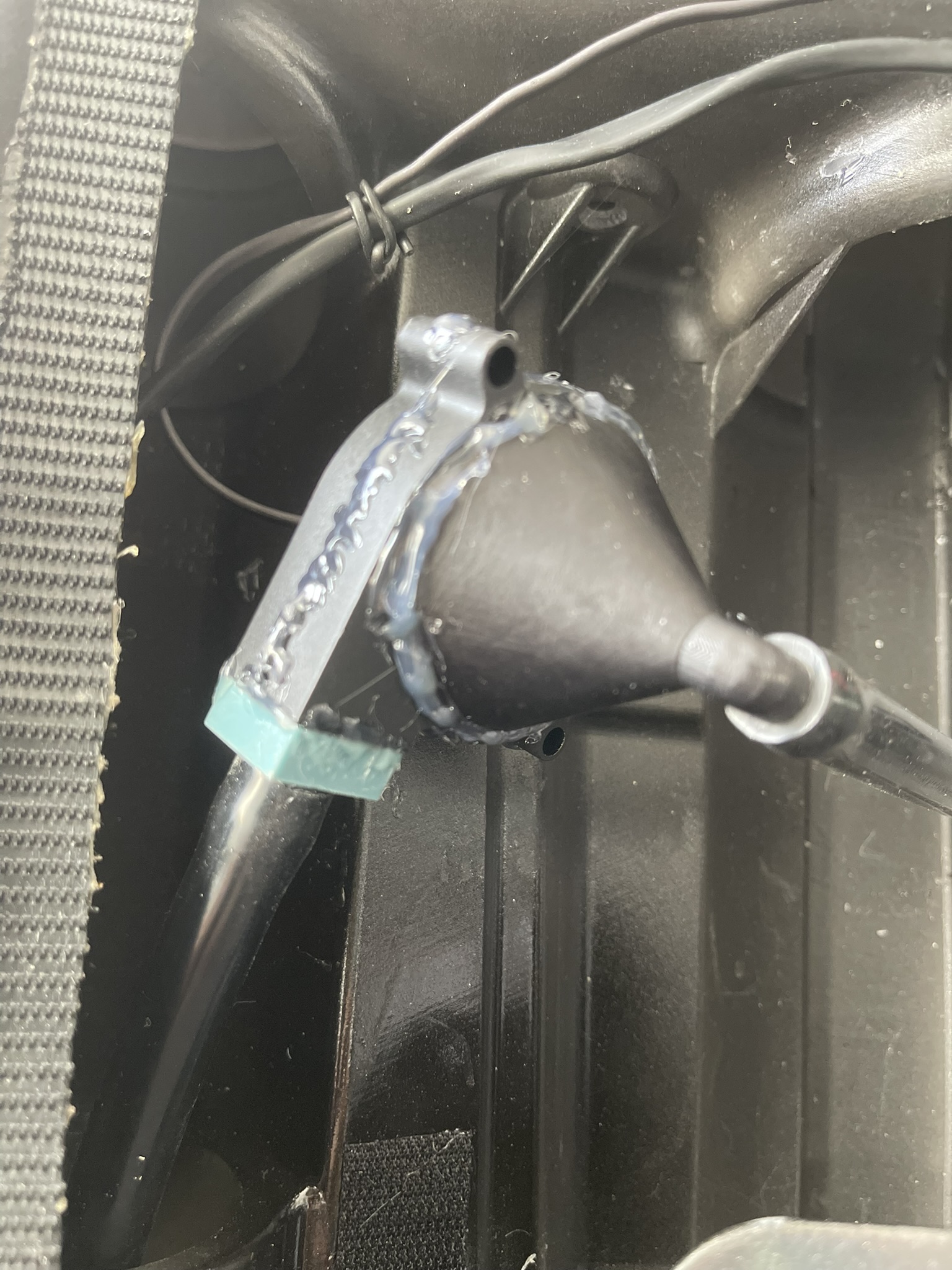
Do a test placement of the fan to measure the lengths of silicone hosing (purchased with your Microfogger if using) and then cut to length.
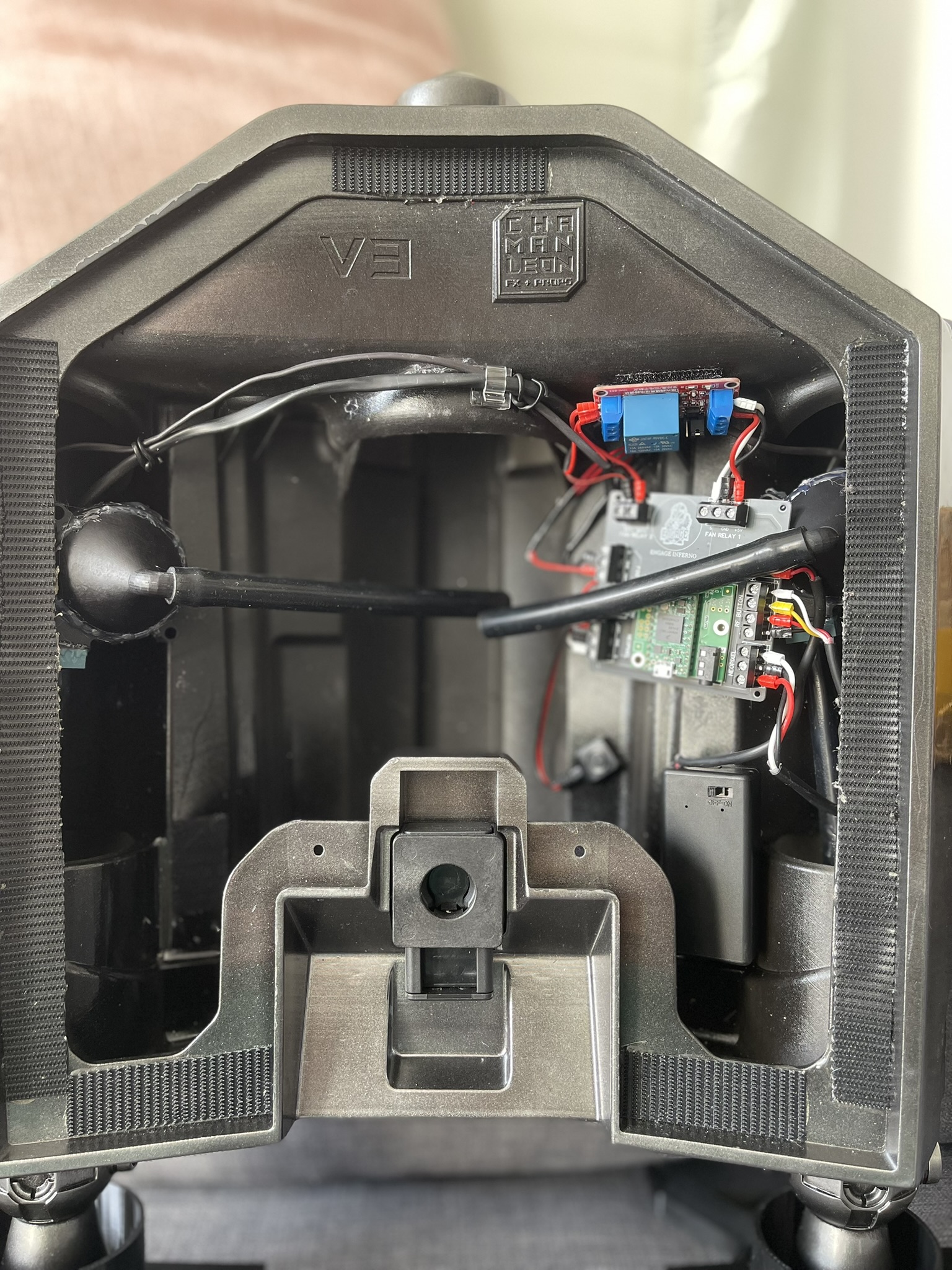
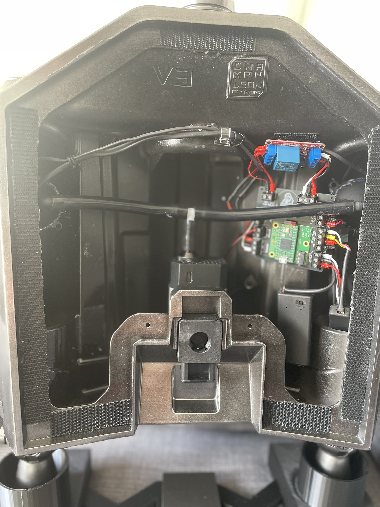
CUTTING HOSES TO LENGTH
Do some practise placements and ensure the silicone hose isn’t too long from the Microfogger to the fan that might add too much strain.
Be careful with the 3D printed parts, excessive force will cause them to break.
When Installing your fans ensure they and the hosing is below the disk locks (if you have them) shown here. These are set back and can add pressure causing damage when the back plate is mounted.

TESTING
Once installed your fans can be connected to the PCB. The final stage is to mount your power pack and connect it and your speaker and confirm everything is working as expected. If installing the Microfogger this will stay in place by the fan hosing and doesn’t need to be set/Velcro in place. This is important in case it needs to be removed and refilled.

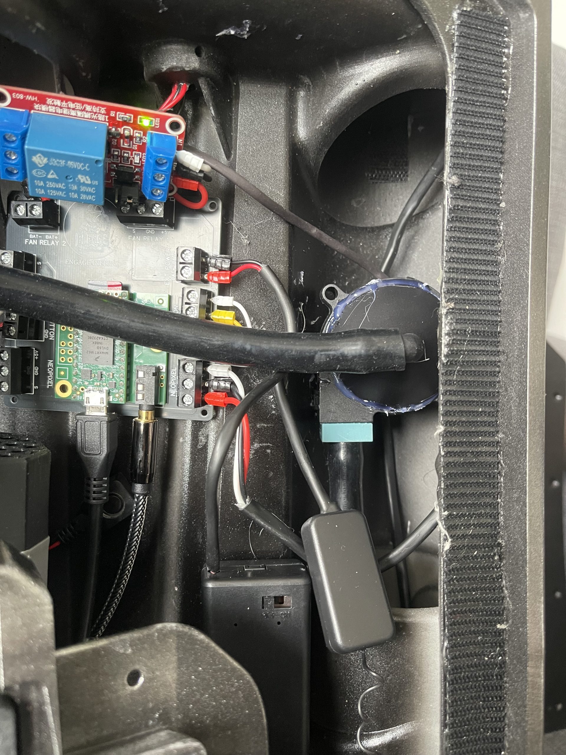
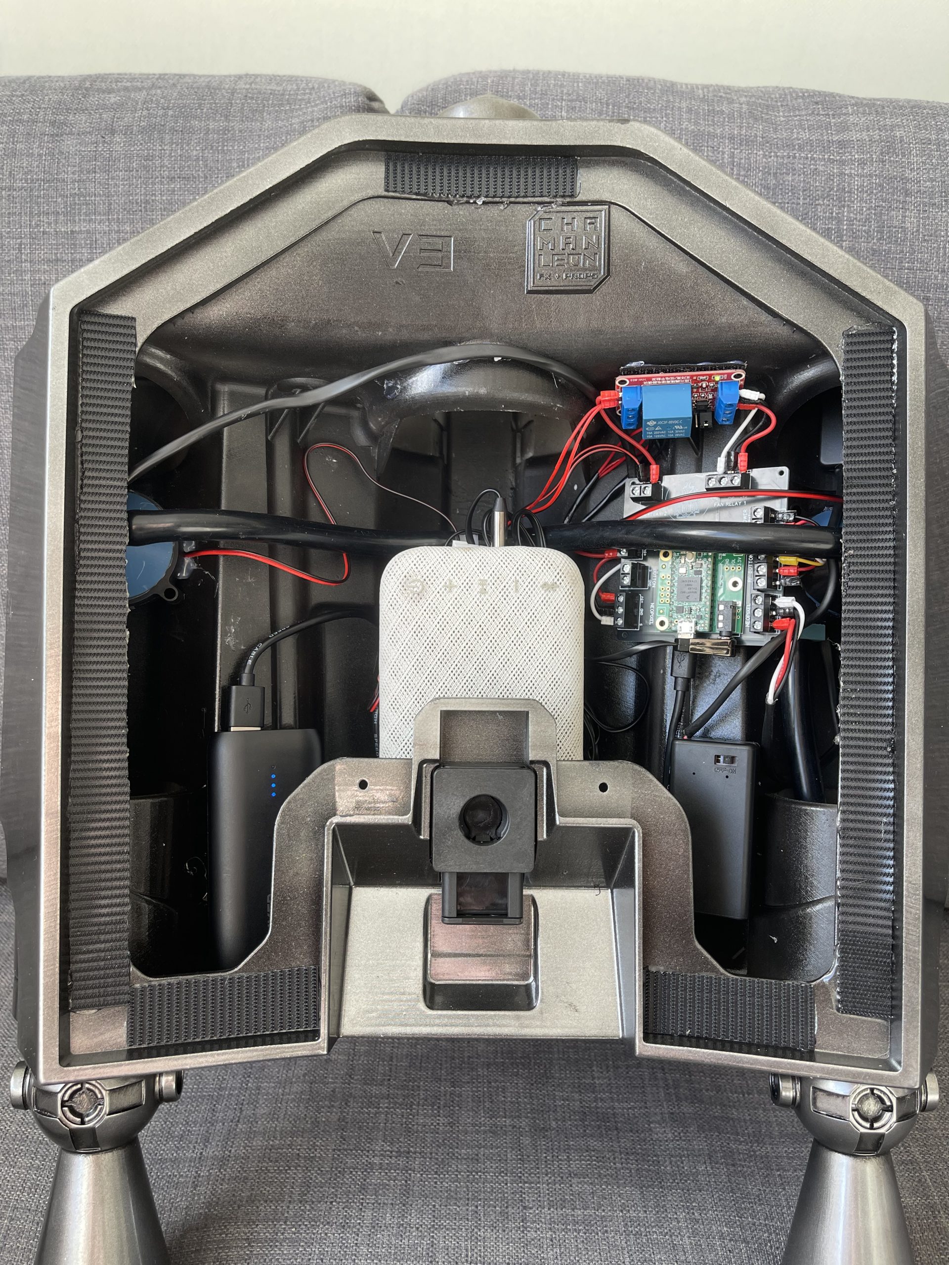
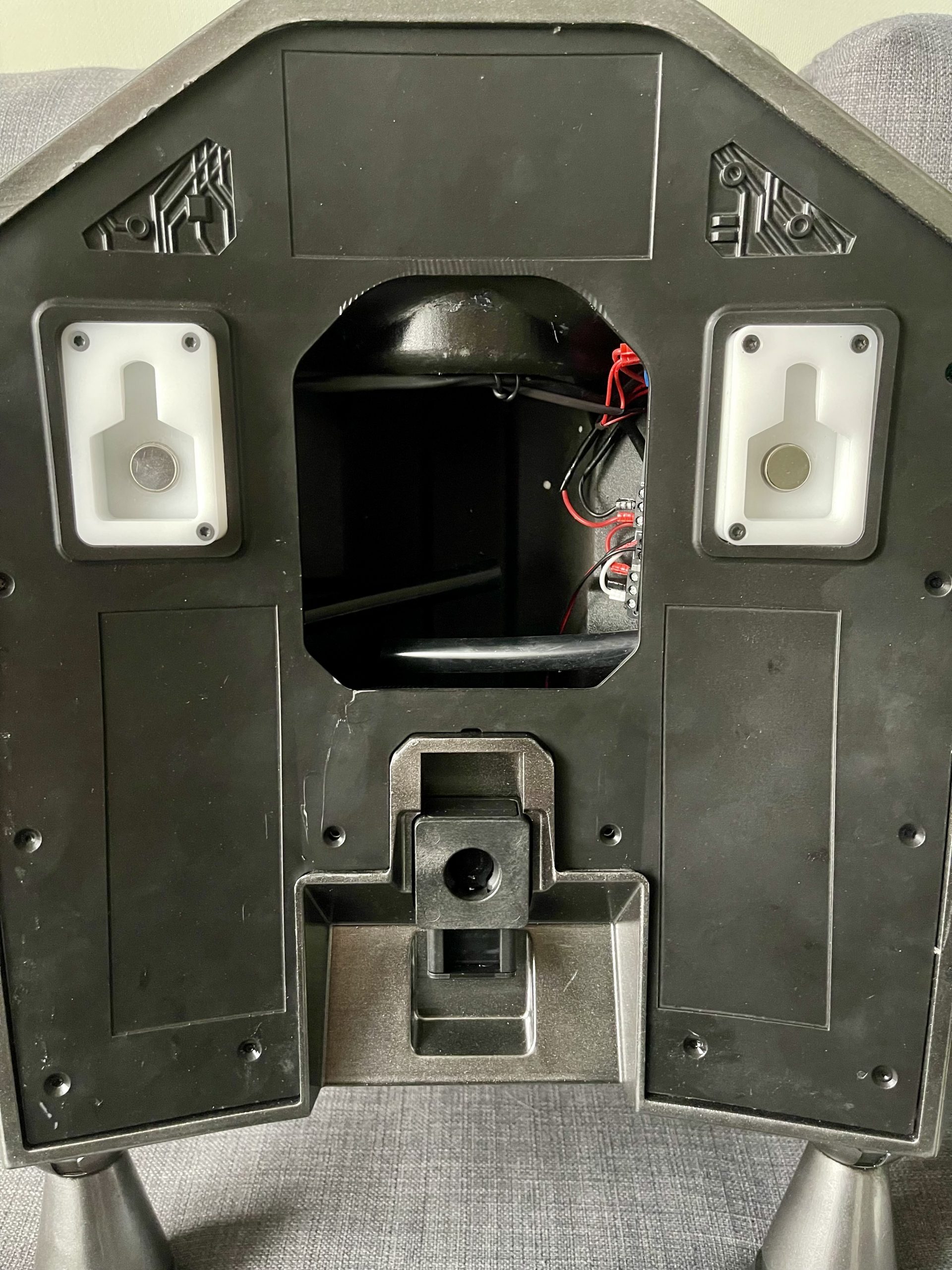
Powering on is as simple as connecting the speaker and power pack. An announcement can be heard stating the unit is online. It can then be activated either by the test button or RF Fob.
Was this article helpful?
Your feedback helps us improve these guides.